IDENTIFYING GROUNDWATER THREATS FROM IMPROPERLY ABANDONED BOREHOLES
R. Kubichek1, J. Cupal1, S. Choi1, W. Iverson2, and M. Morris1
1Electrical Engineering Department, University of Wyoming, Laramie, WY, Ph: 307-766-2240; 2Subsurface Engineering, 14802167th PL SE, Renton WA., Ph: 206-204-7961
Abstract
The University of Wyoming has investigated techniques to determine the status of plugged and abandoned wells. Proper abandonment requires that cement plugs be carefully positioned within the borehole to prevent contamination of aquifers by toxic fluids from adjacent rock formations. The plugs seal off aquifer layers and prevent transmission of fluids through the borehole between formations. Such techniques may eventually be used in wellhead protection programs to determine whether abandoned wells require mitigation, and by enforcement agencies to verify compliance of regulations.
In this approach, a down-going acoustic pulse produces reflections at plug boundaries. Up-going reflection energy is detected by surface acoustic sensors and used to estimate plug size and location. Initial experiments used an artificial borehole constructed horizontally on the ground using well casing. Computer modeling has been used to help interpret reflection signals. Field experiments were conducted during the summer of 1996 on a variety of plugged and unplugged wells. Initial results have been mixed. In some cases, possible reflections are seen from the bottom of the surface plug and the top of the next deeper plug. However, determining whether acoustic events are actual plug reflections or due to other acoustic sources is difficult.
Keywords: cement plugs, boreholes, contamination, acoustic sensors
INTRODUCTION
Each year many wells are plugged and abandoned throughout the United States. These include water wells, mineral exploration wells, and oil and gas production wells. Many wells penetrate one or more aquifers, i.e., layers of sand, gravel, or permeable rock containing potable subsurface water. The wells also pierce formations containing oil and gas reservoirs, mineral deposits such as uranium and lead, and water contaminated with concentrations of salts and other dissolved solids.
The borehole provides a mechanism for communication of fluids and gasses between formations, and therefore poses a threat to fresh water aquifers. For example, if the borehole passes through both an aquifer and a brine-bearing formation, the brine can invade the aquifer and compromise the quality and purity of the water. Aquifers are typically isolated by non-permeable formations above and below the water-bearing material, confining the water and protecting it from contamination. Improperly plugged wells compromise aquifer integrity by destroying its natural isolation, and exposing it to potentially toxic materials from nearby formations.
Preferred or Mandated Abandonment Procedures
Well abandonment procedures have been developed to prevent communication of fluids between formations via the abandoned borehole to avoid damage to fresh-water aquifers. These usually require that wells be plugged with concrete, bentonite, or other dense material. One-hundred-foot-long cement plugs are used in oil and gas wells at 1000- to 2000-foot intervals. Aquifer formations are either sealed off by continuous cement plugs, or by plugs placed above and below the formation. Dense fluids such as drilling mud are used to fill the spaces between borehole plugs. A smaller plug, 30 to 100 feet in length, seals the borehole at the surface. Costs of following proper abandonment procedures vary widely, but can range from a few tens of thousands to well over one hundred thousand dollars.
Oversight Responsibility
Responsibility for proper plugging and abandonment of wells usually belongs to the well operator or owner. Depending on the type of well, oversight of abandonment procedures falls under several jurisdictions. For example, in Wyoming, the State Engineer's Office is responsible for water wells. The Wyoming Department of Environmental Quality (DEQ) has responsibility for stratigraphic test and exploration wells, while the state Oil and Gas Conservation Commission monitors oil and gas wells. The U. S. Bureau of Land Management (BLM) oversees wells on federal lands. Each agency may have a different set of abandonment procedures.
Enforcement of proper abandonment procedures is problematic due to the number of agencies involved and their sometimes-overlapping jurisdiction. Limited resources mean that it is seldom possible for an inspector to be present to ensure proper plugging practices are followed, and the majority of abandoned wells are plugged without any oversight.
Unfortunately, considering the high cost, limited inspection, complicated jurisdiction, and conflicting abandonment procedures, there is temptation to abandon the well with nothing more than a surface plug. Wells abandoned 20 or more years ago are even more likely candidates for improper abandonment due to fewer requirements and less sensitivity to environmental concerns.
Identification of Improperly Abandoned Boreholes
In order to develop effective wellhead protection programs, it would be very useful to know whether regional plugged wells have been properly abandoned, or if mitigation is needed to protect local aquifers. The only practical way to confirm whether a well has been properly plugged is to re-drill it. This is an expensive procedure with costs ranging anywhere from $20,000 to over $50,000. Clearly, a remote sensing system able to identify and characterize the size and location of borehole plugs would be of great interest.
Since fall of 1995, the University of Wyoming has been studying the feasibility of remotely detecting borehole plugs using acoustic sensors. The project has investigated the production of guided or casing waves in the borehole, and detection of reflections from subsurface plugs via acoustical sensors at the surface. So far, a great deal has been learned about the problem, but results have been mixed. No previous investigations on this problem have been reported in the literature, and it is the authors' hope that other researchers will begin to focus on this important problem.
This paper describes the theory, techniques, and results of the research project to date, including computer simulation results and field experiments conducted over the past year. Section 2 provides background on the proposed technique; Section 3 describes the experimental approach along with example results; and Section 4 summarizes the status of the project.
THEORETICAL CONSIDERATIONS
Wave Propagation
Traditional seismic exploration uses low-frequency acoustic plane waves (< 100 Hz) to probe subsurface geology; however, it is unlikely that such techniques could detect small reflecting surfaces on borehole plugs due to resolution limitations, high attenuation from spherical divergence, and interference from larger subsurface reflectors. In contrast, acoustic energy carried by guided waves confined to the borehole are subject only to leakage and frictional losses, and do not suffer the geometric attenuation afflicting plane waves. Examples include casing waves and tube waves, which exist at the boundaries between the fluid interior and the borehole wall. These transmission modes may provide the additional information needed to detect subsurface plugs.
Guided acoustic waves are well known in Vertical Seismic Profiling (VSP) and acoustic logging work as strong sources of unwanted noise that obscure weaker desirable reflections from surrounding strata. However, the very attributes that make them a nuisance in VSP and acoustic logging (e.g., high amplitude and confinement to the borehole) make them well suited for this application. Such guided waves represent our best hope of learning the size and location of down-hole plugs using surface-based tests.
Modeling
The structure of the received geophone signal is very complex, being made up of both primary reflections from each plug surface, and secondary reverberations that occur when energy reflects back and forth between the plugs. To help determine the origin of each reflection event, two computer programs were written to model the flow of sound energy within the borehole. The first model computes a synthetic geophone signal, as well as showing the location of sonic pulses as they travel through the borehole in the form of a Synthetic Vertical Seismic Profile (SVSP). The casing is treated as a series of infinite-layers, each with different acoustic properties (Wyatt, 1981). Although the system is useful for generating quick estimates of reflection arrival times, it greatly over-simplifies borehole geometry. As a result, some important wave propagation modes are not represented, and computed reflection strengths are not consistently accurate.
To better represent borehole sound propagation, we also employ a finite-difference modeling program (FINDIF) that provides a discrete solution of the elastic wave equation, and thus accurately computes all wave modes including guided waves (Cheng, et al., 1995). The main disadvantage of this approach is the heavy computational load and extensive memory requirements, resulting in large computer run times. FINDIF is being used to investigate how sonic pulses pass through cement plugs and how to process the reflection signals for best detection results. Examples of these modeling approaches are shown in subsequent sections.
EXPERIMENTAL APPROACH
Artificial Borehole
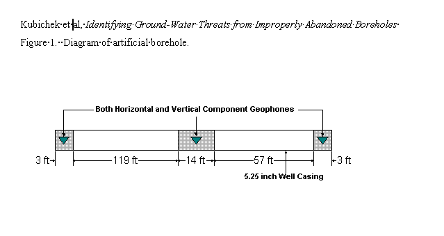
During the early stages of the project, a simulated borehole was developed for evaluating acoustic sensors, data acquisition techniques, and signal processing methods. The test bed allows experiments to be performed in an environment where the plug dimensions and locations are known exactly. The borehole was constructed on the University of Wyoming Animal Science Farm outside of Laramie using approximately 200 feet of 5.25 inch steel well casing. The casing includes cement plugs at each end, and a single cement plug near the center. Acoustic sensors have been installed in each plug to measure vibrations traveling along the casing. Spigots have been installed so that the unplugged sections can be flooded with water to simulate fluid-filled sections of actual boreholes. Tests using the artificial borehole have the following objectives: (1) assess the effectiveness of the acoustic sensors (geophones) and determine the best geophone orientation, i.e., transverse or longitudinal, (2) determine the spectrum of the sonic pulses, (3) measure signal and noise levels, and (4) determine whether plug reflections can be detected in the measured data. A diagram of the setup is shown in Fig. 1. An example acoustic recording from the test bed, along with a synthetic model prediction are given in Fig. 2.
Recording Setup and Processing
Acoustic reflections are recorded using a geophone device chained to the surface casing or steel marker post. The device consists of two series-connected geophones embedded in a concrete container. The container provides mass damping to help suppress ringing when the casing is struck. Three geophone sensor pairs are included in the package and aligned to measure vertical, transverse, and radial vibration components. To further reduce ringing effects, sandbags are strapped to the marker post above the sensor attachment. The three sensor channels are sampled using a PC-based analog-to-digital converter running at 10,000 samples per second per channel, and the data is stored for later processing. Between 5 and 15 records are made for each experimental condition. Acoustic impulses are generated using a large hammer applied either to the top of the marker post or to the steel plate welded to the top of the surface casing. Generated waveforms are remarkably consistent from one hammer blow to the next, indicating low ambient noise levels. Typical post-processing steps include averaging of multiple records to reduce noise, low-pass and band-pass filtering, and deconvolution to further alleviate ringing.
Field Tests
A variety of plugged and unplugged wells was tested during the summer of 1996. The goal was to understand sound propagation in these real world environments, and determine the feasibility of an acoustic approach. Selected examples are presented and discussed in the following sections.
Unplugged Water Well
The citizens of Elk Mountain have kindly allowed us to test several plugged and unplugged wells located near their town. Figure 3 shows a diagram of their newly-drilled water well. This 3000-foot-deep cased well represents an advantageous test site because of its simple structure and detailed available documentation. Figure 4 displays the transverse component acoustic data, and clearly shows the primary well-bottom reflection at 1.5 seconds, along with two multiple path reflections. These strong reflections are convincing evidence that guided waves are being generated and recorded in the borehole.
Medicine Bow #1 Well
Two wells were tested near the town of Medicine Bow, Wyoming. These are presented here as examples of the broad range of configurations commonly encountered with oil and gas wells. The well in Fig. 5 has multiple casing layers, some of which have been cemented to the hole or to adjacent casings. This complex structure makes it very difficult to accurately predict the nature of acoustic propagation. Figure 6 shows a set of data records where each data trace corresponds to a single hammer blow. Using an approximate velocity of 10000 fps, reflections would be expected from surface plug discontinuities at 30 and 67 ms. The data shows large coherent reflections at about 35 ms which may be related to a reflection from the bottom of the surface plug. A much weaker event can be seen at about 65 ms, but it is much less convincing. Since these events could also be due to reflections from rock layers at approximately the same depth as the plug, additional geological information about the near surface would be useful to complete the interpretation.
Medicine Bow #2 Well
A second well south of Medicine Bow was also investigated. As seen in Fig. 7, this well's structure is significantly simpler than the previous well, suggesting that the resulting data may be easier to interpret. However, example results shown in Fig. 8 are quite puzzling. Here, several weak coherent events are seen that could be associated with plug surfaces. Closer inspection shows a 6 ms reverberation that persists throughout the data set. To learn more about the nature of this problem, we drilled a hole through the steel surface plate and found that the cement apparently subsided after the surface plug was poured, resulting in a 3-foot air gap above a 12-foot water column. Multiple reflections in these sections could produce the unwanted 6 ms reverberation.
CONCLUSIONS
Unwanted acoustic energy such as ringing of the casing and multiple reflections from near-surface boundaries make it difficult to identify reflections in the raw signal. Simple band-pass filtering and smooth software gain have shown promising results, but plug reflections still cannot be determined with certainty. Overall, findings based on the raw data have been mixed. The best results were seen on tests of an unplugged water well, where strong reflections were seen from the 3000-foot-deep well bottom. Acoustic records from the plugged wells have been more challenging to interpret. In some cases. possible reflections are seen from the bottom of the surface plug and the top of the next deeper plug. However, it is difficult to determine whether a particular acoustic event is an actual plug reflection, or whether it is due to other sound sources such as ringing from the casing or reflections from subsurface strata.
One possible clue about the small number of strong plug reflections is that typical hammer source energy lies predominately below 2 kHz. However, we expect that best plug reflections will result from guided wave modes that stay confined to the borehole. Such modes are usually generated at frequencies above 5-10 kHz (Cheng and Paillet, 1991), and therefore they are probably not being strongly excited by the hammer source. FINDIF simulations provide a better understanding of how guided waves behave in plugged boreholes. As an example, Fig. 9 shows a simple model involving three small plugs located at 2, 10, and 14 meters depth within a 20 cm diameter hole. Short vertical dimensions are chosen to reduce extended computer run time. The model is radially symmetric, with the borehole center line shown on the far left, the borehole wall at 0.1 m, and an absorbing boundary (required to suppress model edge reflections) extending from 0.6 m to the right edge of the model. The 2 cm square grid size requires 1 microsecond. time steps for stability when using a 15 kHz Gaussian-derivative source. Figure 10 shows a simulation result for the radial velocity component of motion with acoustic sensors positioned down-hole at 40 cm increments (y axis) and simulation time in ms (x axis). The surface sensor trace is shown in Fig. 11. Figures 10 and 11 indicate strong reflection energy from both the bottom of the surface plug and the top of the middle plug. Furthermore, the slower guided wave modes are much stronger then the dispersive compressional wave. It is of interest to note the complexity of the generated wave field due to a variety of mode conversions.
These simulations motivate using higher frequency source energy than is possible using a simple hammer. However, frictional losses increase rapidly as a function of frequency, limiting the maximum usable frequency to probably less than 20 kHz. Therefore, for the final phase of this project, we are testing piezo-electric transducers operating at 6 and 13 kHz to use as acoustic sources and sensors. The main advantage will be generation of a repeatable source signal with significant high-frequency content. Such a source should not excite the low-frequency vibrational modes associated with casing ringing, and we believe will result in much cleaner, higher resolution records. More importantly, the new sources may better excite guided wave modes resulting in stronger plug reflections.
ACKNOWLEDGMENTS
The authors would like to express their appreciation to all the individuals and organizations who have provided assistance. In particular, thanks are due to Kip Purinton and the U. S. Bureau of Land Management, the citizens of Elk Mountain, Todd Jarvis of Weston Engineering, and the University of Wyoming Animal Science Farm. The research is supported under a grant from the Hazardous Substance Research Center, Kansas State University, Project 94-24.
Although this article has been funded in part by the U.S. Environmental Protection Agency under assistance agreement R-819653, through the Great Plains/Rocky Mountain Hazardous Substance Research Center headquartered at Kansas State University, it has not been subjected to the agency's peer and administrative review and therefore may not necessarily reflect the views of the agency, and no official endorsement should be inferred.
REFERENCES
Cheng, C.H. and F. L. Paillet, Acoustic Waves in Boreholes, CRC Press, 1991.
Cheng, N., C. H. Cheng, and M. N. Toksoz, "Borehole wave propagation in three dimensions," J. Acoust. Soc. Am. 97 (6), pp.3483-3493, June 1995.
Wyatt, K. D., "Synthetic vertical-seismic-profile," Geophysics, 46, no. 6, 880-891, 1981.

Figure 1. Diagram of artificial borehole.
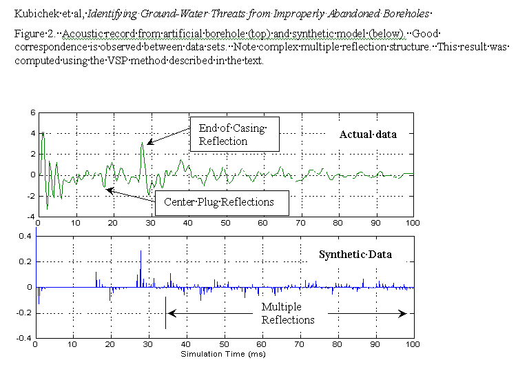
Figure 2. Acoustic record from artificial borehole (top) and synthetic model (below). Good correspondence is observed between data sets. Note complex multiple reflection structure. This result was computed using the VSP method described in the text.
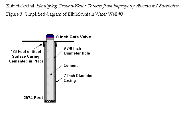
Figure 3. Simplified diagram of Elk Mountain Water Well #3.
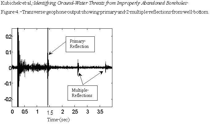
Figure 4. Transverse geophone output showing primary and two multiple reflections from well bottom.
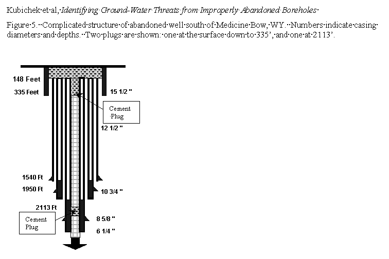
Figure 5. Complicated structure of abandoned well south of Medicine Bow, WY. Numbers indicate casing diameters and depths. Two plugs are shown: one at the surface down to 335’ and one at 2113’.
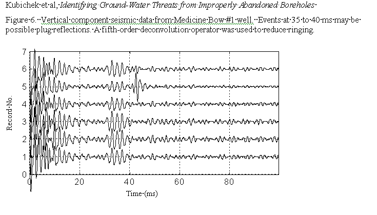
Figure 6. Vertical component seismic data from Medicine Bow #1 well. Events at 35 to 40 ms may be possible plug reflections. A fifth-order deconvolution operator was used to reduce ringing.
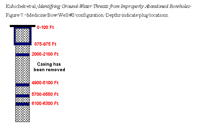
Figure 7. Medicine Bow #2 well configuration. Depths indicate plug locations.
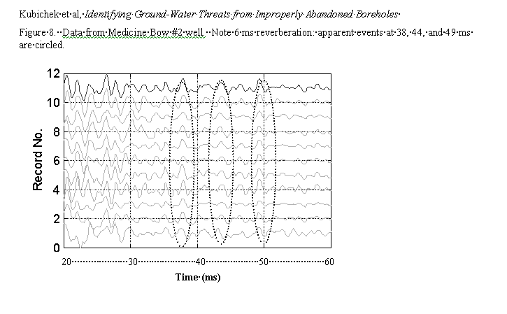
Figure 8. Data from Medicine Bow #2 well. Note 6 ms reverberation: apparent events at 38, 44, and 49 s are circled.
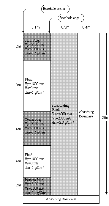
Figure 9. Three-plug finite difference model.
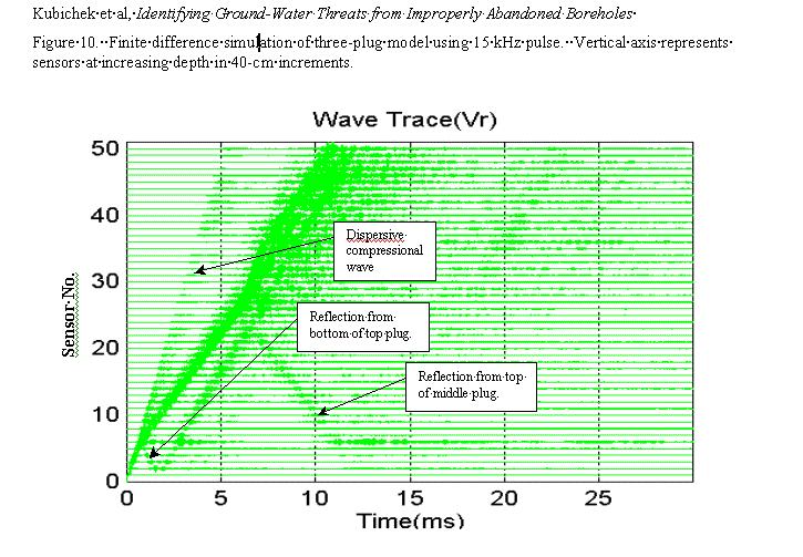
Figure 10. Finide difference simulation of three-plug model using 15kHz pulse. Vertical axis represents sensors at increasing depth in 40-cm increments.
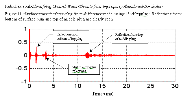
Figure 11. Surface trace for three-plug finite-difference model using 15kHz pulse. Reflections from bottom of surface plug and top of middle plug are clearly seen.